
Improving Cycle Time with Veo FreeMove
By Alberto Moel (Vice President Strategy and Partnerships)
Welcome back, dear reader, to one more installment of the Veo Robotics blog. In our previous edition, we laid out a general model of human-robot collaboration driven by the manufacturing application’s process cycle time[1] and the frequency of human interaction.
In our model, the design and operation of the application will determine how and how often the human and robot will collaborate. At one extreme, there is no collaboration, and the application runs unattended[2] throughout the operating cycle. At the other end, human interactions can occur multiple times a cycle, as in a parts presentation for assembly application. We concluded that the shorter the cycle time and the more frequent the required human interaction the more collaborative the application.
If we could optimize this interaction time, we would improve the efficiency of the human-robot collaboration, lowering production costs and enhancing manufacturing economics. In today’s post we will quantify (through a simple case study) how the economic benefits of Veo FreeMove increase with the application’s degree of collaboration; in other words, the more you need humans in your process, the more Veo FreeMove can improve the economics of your application. And as we show in Figure 5, the incremental production rates enabled by Veo FreeMove can be quite large.
The case study – original configuration
A parts manufacturer was looking to improve the productivity of a machine tending workcell through better human-robot collaboration. The workcell was designed for an industrial robot to move the front panels of a circuit breaker to and from a laser cutting machine, a typical metal fabrication operation.
In this process flow, a human brought in a pallet rack of unprocessed parts to be laser cut, then the robot picked up a part from the pallet rack, inspected it, and if it passed QC, loaded it into the laser cutter. Defective parts were dropped on a separate pallet. When the laser cutting was finished, the robot unloaded the part and placed it on an output pallet for the human worker to withdraw when full.
As shown in Figure 1, the robot had access to five pallet racks for unloading materials and loading parts: the two on the left for raw materials, the two on the right for the finished parts, and the center pallet rack for defective parts. Full or empty pallets were replaced by the human operator as required.
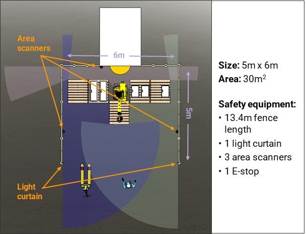
Figure 1. Case study original workcell architecture.
Ensuring that these kinds of collaborative robotic workcells are safe for human entry requires the integration of safety systems in addition to the robot, fixturing, and programming for the application itself. In this case, to allow operators to safely enter and exit, the workcell was safeguarded by three 2D area scanners guarding planes perpendicular to the fences, and one light curtain set at the entrance of the workcell, serving as a virtual fence.
Designing and implementing a workcell with these disparate safeguarding elements is time consuming, requiring extensive ladder logic development, testing of possible breach sequences, calculations of protective separation distances, and risk assessments. The design and implementation is also inflexible, and as we have previously discussed, the flexibility to quickly and easily reconfigure a workcell is immensely valuable.
To exchange a pallet or perform maintenance inside the workcell, an operator would have to breach the light curtain, triggering the robot to stop the moment the operator entered the workcell (Figure 2). The robot could only restart once the operator had completed their task, fully vacated the workcell and pressed a button to resume operations.
The Protective Separation Distance (PSD), according to manufacturing safety standards, is the minimum distance between a human and a robot at which the robot is required to stop to ensure the safety of the human. Traditional sensing devices (like light curtains and area scanners) use static PSDs that are set based on the worst-case scenario (in this case, when the robot arm is fully extended toward the front of the workcell and a human is approaching it directly).
Additionally, workcells guarded by traditional sensing devices are typically designed to require manual restarting to avoid additional complicated application design, engineering, and risk assessment—all of which contribute to a lengthy process and higher set-up costs.

Figure 2. Sensors trigger robot shutdown when static PSD is violated.
With traditional sensors and a static PSD, each human entry event would cause the robot to stop for the time it takes the operator to move between the entry point of the workcell and the location of the task, plus the time it takes to complete the task, plus the time it takes to exit the workcell, plus the time it takes the operator to visually check for a safe state and press the manual restart button (check out one of our other blog posts for more on inefficiencies caused by downtime).
The case study – the Veo FreeMove configuration
One option to reduce downtime, improve productivity, and boost revenue is to incorporate Veo FreeMove as part of the workcell design. Unlike traditional sensing devices, FreeMove is a single, comprehensive system that monitors a complete volumetric safeguarded space, enabling dynamic PSD monitoring.
A dynamic PSD is calculated based on the actual positions of the robot and human, derived from the 3D state of the workcell as observed by FreeMove Sensors mounted on its periphery (Figure 3). FreeMove’s real-time understanding of the space enables dynamic computation of the extent of the robot hazard, which changes with the position and speed of the robot and workpiece. The FreeMove Engine uses the 3D data to identify where the robot, workpiece, humans, and any occlusions are in the workcell. It then calculates all possible future states of the workcell and signals the robot to stop if a human might violate the PSD.

Figure 3. New workcell architecture with Veo FreeMove.
When FreeMove determines that it is safe for the robot to move again, it signals the robot to restart automatically. FreeMove supports safe and reliable automatic restart because it monitors the workcell in 3D and can predict safe and unsafe states in real time. Consequently, the robot can continue operating until a human violates the dynamic PSD (Figure 4).

Figure 4. FreeMove triggers a robot stop when the dynamic PSD is violated.
Using a dynamic PSD results in shorter average PSDs, which means less downtime when the robot is not working, and greater productivity of the workcell as a whole. A human operator can get much closer to the robot before it stops, so the robot operates for more time during each human entry event. If the timing is right, a human operator can even reach one of the pallet racks before FreeMove deems it unsafe and stops the robot. After the operator finishes the task, steps away, and reinstates the PSD, FreeMove signals the robot to restart.
For this workcell, we estimate that the average distance between the robot and human before the robot is triggered to stop is about 1.3 meters with FreeMove, compared to 3.9 meters with traditional sensing devices. This means that with FreeMove the robot can continue to operate for the time it takes a human operator to travel an additional 5.2 meters (round trip), which translates into a downtime reduction of 4 seconds per event, relative to traditional sensing devices.
What can FreeMove do for you?
Using FreeMove, we are able to shorten the cycle time by roughly 4 seconds from the traditional configuration by reducing the minimum distance between the human and the robot at which the robot has to start stopping.
What does this mean in a more general case? Imagine a thought experiment where the above example generalizes to a continuum of applications, where both the cycle time and the frequency of human interactions per cycle can vary, but we keep the 4 second cycle time benefit from Veo FreeMove. Intuitively, the shorter the baseline original cycle time and the higher frequency of human interaction the higher the benefit of Veo FreeMove on production economics.
How much of a benefit? Figure 5 shows the incremental unit production allowed by the shorter cycle time for three human interaction frequencies per cycle (2x per cycle, 1x per cycle, and once every 2 cycles). As we can see, the value of FreeMove increases rapidly as cycle times are reduced and human interaction increases. Even for relatively “long” cycle times (say, 60 seconds or more) incremental capacity can be in the 10-20% range which is a major improvement in productivity in many real-world situations.

Figure 5. Incremental production enabled by Veo FreeMove as a function of cycle time and human frequency interaction.
Another thought experiment would be, instead of modeling the interaction frequency, to allow for different cycle time savings. Figure 6 shows examples of the incremental productivity as we vary the cycle time savings along a range of realistic cycle times, assuming human interaction once per cycle.
As we can see, for a range of realistic cycle times, productivity improvements from even a few seconds of improvement in cycle time can be material. This can make a substantial difference in manufacturing environments where the economics are marginal, and a 5-10% improvement in productivity is the difference between profit and loss.

Figure 6. Incremental production enabled by Veo FreeMove as a function of cycle time and cycle time savings for 1x per cycle human interaction.
[2] Except possibly for routine maintenance or unexpected repairs.