
How Snappy Is Your Robot? Part 2
By Alberto Moel (Vice President Strategy and Partnerships)
Welcome back, dear reader, to one more installment of the Veo Robotics blog. In our previous post, we went into the weeds into how the Protective Separation Distance (PSD) required for safe human-robot interaction between the human operator and the moving robot varies with robot controller latency.
We found that robot controller latency has a material and negative effect on the PSD and, hence, how collaborative a robot can be. Not only does controller latency linearly increase the minimum PSD (the PSD at zero robot velocity), but there is a negative interaction between robot controller latency and robot velocity beyond a simple additive term – increasing latency worsens the impact of robot speed on the PSD.
As an example (taken from Figure 2 of the previous post) a robot controller latency Tr of 50ms at a robot velocity vr of 2 m/sec gives us a PSD of 91cm. On the other hand, an (admittedly extreme) controller latency of 500ms1 leads to a PSD of 2.5m, making this application not very collaborative2. Very simply, the lower the robot controller latency, the better.
The other driver of PSD is how quickly the robot can decelerate or come to a complete stop given an initial velocity. This is going to be an intrinsic function of the payload, pose, and the fundamental mechanics and kinematics of the robot – how strong its brakes are, the frictional forces at the joints, and even the shape and geometry of the arm.
In today’s post we will continue our analysis of the PSD, this time focusing on how the robot deceleration impacts the PSD. The rest of the post lays out the math and analysis, but if you feel like stopping3 now, we find that robot deceleration does not have an impact on PSD if the robot Tool Center Point (TCP) deceleration as is fast enough (practically, higher than 20-30m/sec2. As we show below, these kinds of decelerations are easily achievable in practice by industrial robots.
As a result, we conclude that the robot controller latency is a bigger driver of PSD than robot deceleration. This calls for robot manufacturers to focus on improving controller latencies rather than robot stopping kinematics, and is consistent with our findings that PSDs are relatively insensitive to robot payload and reach.
To be clear, Veo FreeMove® calculates PSDs by taking the robot pose, maximum joint accelerations, etc. into account when building the Robot Future Cloud (RFC), which is the potential volume the robot could occupy in the future given its current pose. This is quite a complex dynamic calculation that FreeMove® runs in real time using conservative maximum values for stopping times provided by the robot manufacturer.
The logic here is that the entire robot (not just the TCP) is the hazard to protect from, so what is relevant are the simultaneous dynamics of all the robot joints as the stop command is executed. Veo FreeMove® calculates these potential positions for the entire robot through the RFC.
For the purposes of analysis in this blog post, however, we do a simple linearization focusing on the TCP as a means to numerically bound the impact of deceleration on the PSD. This approximation cannot be used in a functional safety system like FreeMove® but provides insight into the performance of robots for human-robot collaboration, using TCP deceleration numbers as an illustrative and explanatory proxy. The results are quite similar to what we see from the full calculation performed by the FreeMove® system.
We hope you have enjoyed this recent series connecting robot parameters to how collaborative a robot can be within the safety standards. Up next, we will be moving into some practical guidance on how to determine if an application is amenable to collaborative robotics.
Back to Basics (For the Last Time?) – SSM and PSD

where
Sp(vr) is the PSD for a given robot velocity vr;
vr is the linear robot TCP velocity as it directly approaches the human operator4;
vh is linear velocity of the human operator as it approaches the robot;
Tr is the robot controller latency, the time between the receipt of an external command and the execution of the command;
as is the robot TCP deceleration (in m/sec2) once the robot begins stopping. a_s is a complex function of robot kinematics including pose, payload, and speed, but we can simplify it to a constant deceleration as>0. The value for as is taken from product documentation or from experimental data and represents the robot TCP deceleration for a controlled stop. It is used as a conservative estimate for the deceleration at each observed point on the robot arm;
C is the intrusion distance, as defined in ISO 13855; this is the distance that a part of the body can intrude into the sensing field before it is detected;
Zd is the position uncertainty of the operator in the collaborative workspace, resulting from the sensing system measurement tolerance;
Zr is the position uncertainty of the robot system, resulting from the accuracy of the robot position measurement system.
To derive the above formula, we assumed that the operator’s motions will follow a worst-case scenario in that the operator will begin moving in the direction of the robot at any time. Similarly, we assumed that the robot can begin moving at any time towards the human at a velocity vr. A robot stop command must be issued at the instant the actual separation distance S falls below Sp since otherwise the operator would be able to reach the moving robot within the robot’s reaction time Tr.
What are Sensible Values for Robot Deceleration?
In the previous post, we estimated the PSD as a function of robot controller latency T r. This time, we will let robot deceleration a s (which drives stopping time) vary instead. What is a sensible and realistic range for this robot deceleration?
ISO 10218-1 Annex B requires that the stopping time and distance for different dynamic states of the robot (at a minimum, 33%, 66%, and 100% of speed, load, and extension, respectively) be provided by robot manufacturers. The data is provided for the different stop categories, at the very least for a Category 0 stop (where motor power is cut off immediately) and a Category 1 stop (where the robot is decelerated to a stop before the motor power is cut off).
However, these data are generally provided for each joint (in “joint space”), and stopping “distances” are presented in degrees or radians (i.e. what kind of a rotation the robot axis will go through before the joint comes to a stop). To convert to an estimated TCP distance, we can make the simplifying assumption that the TCP is at a fixed radial extension from the center of the J1 (base) joint. In other words, the robot TCP is moving in a circle whose radius is given by the robot extension, and the TCP stopping distance S s is given by the stopping distance in radians times the robot extension length 5 . And, given an initial robot velocity v r and a stopping time T s, we can easily calculate a linear deceleration a s:

What is going to determine if a robot is a slow-stopper6? Robot deceleration is driven not just by the dynamics of the robot (pose and inertial characteristics) but also by how the robot is stopped. We have found that Category 0 stops tend to have higher as than Category 1 stops. Many times, the Category 0 stops are tied to the e-stop circuit and additionally mechanical braking is applied, which further increases as relative to the “natural” deceleration from frictional and inertial forces on the de-powered robot joint.
Over the last few years at Veo we have characterized a number of robots, estimating dynamics either through published stopping data, or through direct measurements from controller data or with motion capture tools. Table 1 shows the range of estimated or calculated linear TCP decelerations (in m/sec2) for several robots we have worked with.
The range is determined by the type of stop (Category 0 or Category 1), initial speed, and payload. But in all cases, we assume that the stopping distance is that of the TCP for a fully extended robot rotating along the J1 base joint. Further, some of these numbers include the controller command latency Tr (those calculated from published data), while others do not (those captured from direct measurements)7. From these data points, we conclude that deceleration values in the 10-100m/sec2 are adequate for our sensitivity analyses.

Table 1. Estimated or calculated robot decelerations
PSD as a Function of Robot Deceleration
We also need an estimate of the robot controller latency Tr. In the previous blog post, we allowed Tr to vary from 0 to 1 second, although values are usually clustered in the 50-100ms range (with maximum observed values of at most 500ms). So, let us pick a reasonable value of 100ms for our analysis. Similarly, as in Part 1, assume vh is 1.6m/sec. based on the specifications in ISO 13855.
We also need estimates for the intrusion distance C and the robot and sensor measurement uncertainties Zr+Zs Since we are Veo Robotics and we have the FreeMove® system, we have determined, from section 6.2.3 of ISO 13855:2010 that C is 88mm, and that Zr+Zs is given by the length of a FreeMove® voxel diagonal, or 130mm. Putting it all together, Table 2 captures our realistic model estimates.

Table 1. PSD calculation parameters used in Figure 1 and Figure 2.
What does the PSD look like as the robot stopping moves from snappy to sluggish? Figure 1 and Figure 2 show the calculated PSD parametrized for initial robot velocity v r and robot deceleration a s. As we can see, at sufficiently quick (but easily achievable) decelerations of 20-30m/sec 2 , the PSD is relatively insensitive to robot decelerations. In other words, the robot stopping time is only a factor in the PSD for slow-stopping robots.
The bigger question is which robot intrinsic parameter – robot controller latency T r or robot deceleration a s – has a larger impact on the PSD, and hence on the “collaborativeness” of the robot. To investigate this, we can parametrize the above equation in 3D space for a fixed robot velocity v r. Figure 3 shows the 3D “envelope” for a robot velocity v r or 2m/sec.
Clearly, the impact of the robot deceleration a s is under 1 meter across the range of sensible robot decelerations (between 10 and 100m/sec 2 ). On the other hand, for the range of observed robot controller latencies (50-500ms), the PSD range is around 2 meters.
Robot decelerations are a function of robot mechanics and kinematics, and are hard to make smaller, as physics (robot payload and inertia) get in the way. Fortunately, we find that easily achievable stopping performance is not a major factor in the PSD. The real culprit of large PSDs is robot controller latencies, which are a function of controller architecture and electronics. Designing low-latency controllers is conceptually possible but would require a rethinking of how robot companies design and develop controllers.
In the meantime, we at Veo Robotics are working on what is commercially available and find that there is a definite opportunity for human-robot collaboration with large industrial robots. In our next post, we will lay out the decisions end users need to consider when contemplating collaborative robotics applications, so stay tuned.

Figure 1. PSD as a function of robot velocity vr parametrized by robot robot decelerationas.

Figure 2. PSD as a function of robot deceleration as parametrized by robot velocity vr.
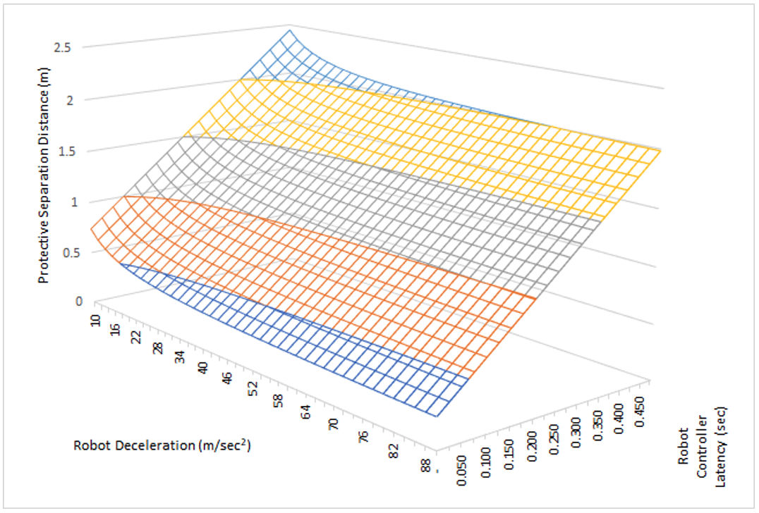
Figure 3. PSD as a function of robot deceleration as and robot controller latency Tr for a robot velocity vr of 2m/sec.
1 Although extreme, we have observed this latency in practice for certain robot controllers and operating conditions.
2Assuming a Tool Center Point (TCP) deceleration of 10m/sec2.
3Sorry, bad pun.
4This linearization assumption is important, as in reality the TCP speed may not be the maximum robot speed (e.g., one of the joints may be moving faster than the TCP). In this model, we simplify by assuming that the human is approaching the TCP from outside the robot envelope directly towards the TCP as the TCP moves in the direction of the human.
5Not to belabor the point, but the TCP velocity calculation here is purely for analytical purposes. Veo FreeMove® does not calculate TCP velocities, but the potential robot position of the entire robot via the Robot Future Cloud.
6All robots are beautiful showstoppers. But not all of them are slow-stoppers.
7The methodology for each specific robot is available upon request. When we do not have direct motion capture data (in particular for some of the FANUC robots) we make assumptions about robot controller latency in order to estimate the stopping time once the robot has begun stopping. Effectively, we need to subtract the robot controller latency from the time the command is issued and the robot comes to a stop, as we are looking explicitly for the time the robot comes to a stop once a stop command is acknowledged. Veo FreeMove® does not calculate or estimate these numbers. It relies on published or experimentally-determined stopping times to determine safe distances via the Robot Future Cloud.